Changing interrupt timer period
 The original Hasselt firmware runs a 10ms timer on Timer0 in interrupt isr_low. The code for Mespelare could use a timer that is a bit less granular than 10ms, for example for the new output PWM routine. Therefor I changed the timer period to 1ms, and updated the other code so it can handle this new timer period.
Configuring the timer
The timer is configured in the function init(), which is called at the start of main().
void init()
{
	...
	// Timer 0 used as 10ms clock tick
	OpenTimer0( TIMER_INT_ON &
				T0_16BIT &
				T0_PS_1_2 &
				T0_SOURCE_INT );

	WriteTimer0(Timer0ReloadValue);
This instruction opens Timer0 with 16 bits of resolution (0 to 65535), and sets the prescaler to 1/2.
To calculate the timer period, we’ll need to understand how the PIC drives the interrupt from its clock source. For more information, check the 18F66K80 family datasheet, section 13.1 Timer0 Operation. For our purpose we need the following basic understanding: at our clock frequency of 8MHz, 10ms means 80.000 clock ticks. Since the prescaler is set to 1/2 this is halved to 40000. To get this precise amount of ticks from a counter that counts to 65.525, we’ll need to preset the counter to 65536 - 40000 = 25536 every time the interrupt is called. This preset value will be stored in the label Timer0ReloadValue, which is defined in vscp_node_defines.h.
//Timer0 used as 10ms timer. Timer generates interupt on overflow.
//#define Timer0ReloadValue 25536  //10ms = 80000 clock ticks at 8Mhz Fosc/4. Prescaler = 1/2. Timer0ReloadValue=65536-40000=25536
To change the timer period to 1ms, we’ll comment out the above line and add a new line:
#define Timer0ReloadValue 61536 //1ms = 8000 clock ticks at 8Mhz Fosc/4. Prescaler = 1/2. Timer0ReloadValue=65536-4000=61536
Once the timer expires, the function isr_low will be called. It tests if the interrupt was cause by timer0 and executes the application code that uses this timer.
void interrupt low_priority isr_low( void ){
	...
	if ( INTCONbits.TMR0IF ) {	// If a Timer0 overflow Interrupt, Then...
	...
	...
	WriteTimer0(Timer0ReloadValue);
    INTCONbits.TMR0IF = 0; //clear overflow IRQ
}
return; }
At the end of the interrupt routine, the timer counter is reset to its starting value and the timer overflow bit is cleared.
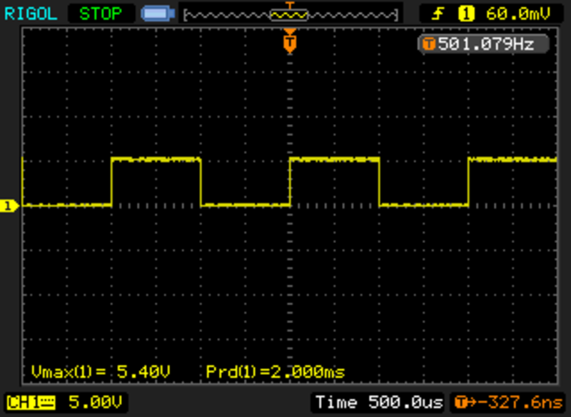
If we toggle a spare output pin inside the inpterrupt routine, we can check on the oscilloscope that our interrupt is indeed running at 1ms. Since we are toggling the pin in the interrupt, a full period of the waveform will need two passes through the interrupt routine. So we’ll need to devide the measured period by 2.
Existing 10ms application code
Ofcourse the original application code, which expects to run at 10ms, is now running at 1ms as well. So we’ll need to modify the interrupt routine to accommodate this.
We’ll use a new variable, counter_1_to_10ms, to count to 10 inside the 1ms interrupt routine.
unsigned short counter_1_to_10ms = 0;  // Counter used to generate counter_10ms from 1ms interrupt

void interrupt low_priority isr_low( void ){
...
	if ( INTCONbits.TMR0IF ) {	// If a Timer0 overflow Interrupt, Then...
        // put 1ms work here

		counter_1_to_10ms++;

        if ( counter_1_to_10ms >= 10 ) {  // if 10ms have expired
            counter_1_to_10ms = 0;      // reset counter for next pass

            //put 10ms work here
Now the original code runs at 10ms again, and we have a place to put code that we want to run at 1ms.